Reinforced Concrete Pedestrian Bridge
This article goes into depth on this course project, the development of a CSA A23.3:19 compliant pedestrian bridge.
Overview of Project
For the Reinforced Concrete 1 class, we designed a pedestrian bridge consisting entirely of reinforced concrete. The bridge has a single supporting pillar offset from its midpoint, and is required to also be safe against earthquake loads. We produced a complete drawing of the bridge, including the reinforcing steel in a manner where the bridge could be realistically constructed. As part of this project, we also designed the foundation and connections between the foundations, pier, and girder. The bridge had a metal railing as well as a drip edge that needed to be accounted for. As part of the final report, we created the reinforcring steel schedule, complete drawings of the bridge geometry and rebar, as well as a report proving the bridge was able to pass various design checks.
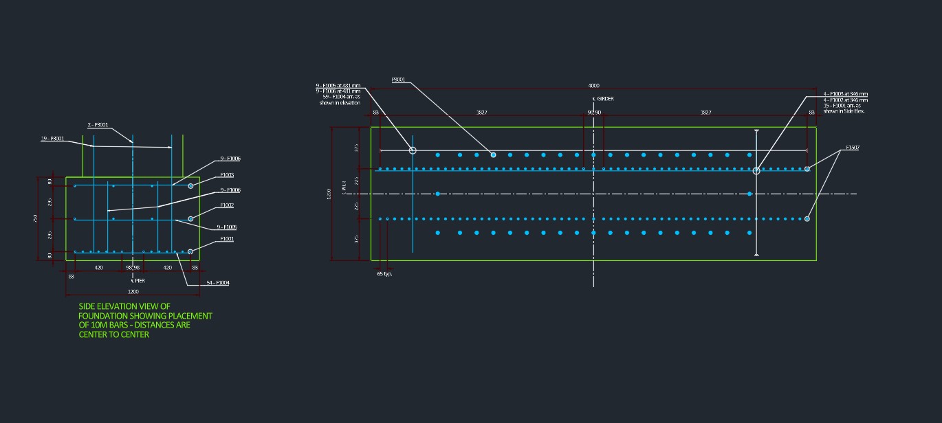 Above: Overview of the main brige design.
Analysis and Design
For the project, we were initially given a plan view of the abutments and location of the pier foundation. From this, we developed the concrete form and overall structure of the bridge, before diving into the specifics of rebar reinforcement. For the rebar, we needed to check a variety of criteria including making sure the rebar would not pull out of the concrete, making sure that there was an adequate amount and size to reduce cracking of the concrete, and also ensuring that an economical amount of rebar and concrete was used. In this project, I mainly focused on the pier design. For the pier, the main criteria dictating the design is the requirement for it to resist seimsic loading. Seismic loading would cause more bending than other load cases, so it is important to ensure that this is properly calculated. With the bridge designed, we reported a fully detailed plan of the bridge, which would allow a builder to create the bridge, as well as a detailed rebar schedule and analysis of critical components to ensure that any potential issues are mitigated.
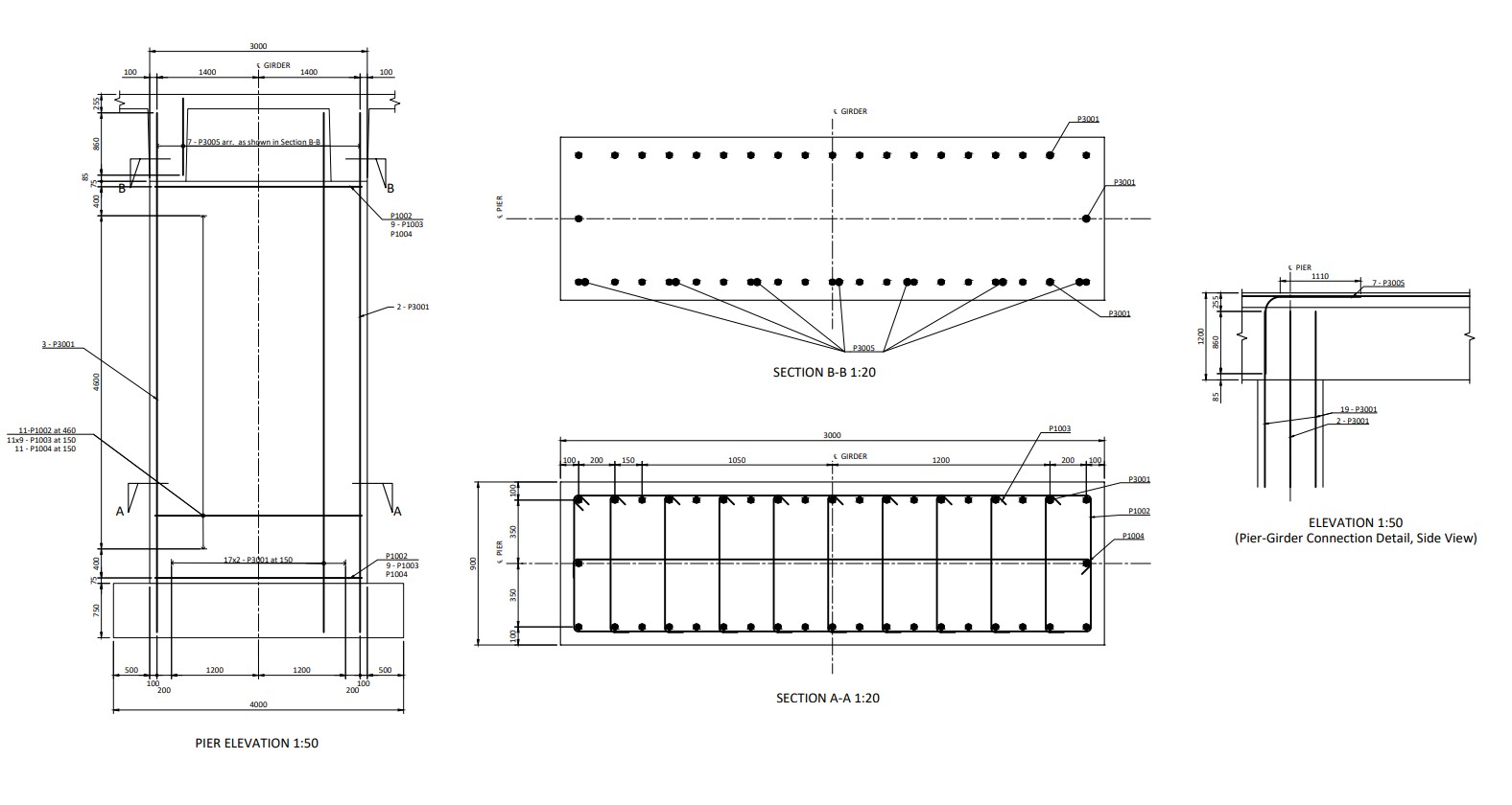 Above: AutoCAD screenshot of pier section detail.
Skills and Use
For the pier design, I used truss models and hand calculations to understand the behavior of the pier, as well as the connections it had to other sections of the bridge girder. I used Excel to speed up the calculation process and generate graphs and intersection diagrams to ensure that all the extreme load cases are within the limits. Once the steel was theoretically designed, I used AutoCAD to draw the pier and connecting steel. For this part, I needed to communicate to my other group-mates to ensure that the connections between our sections is possible, and that there would not be too much steel in one area, for exampele. In addition, much of my time was spend ensuring that the report and drawings were clear, concistent, and comprehensive so that there would be no misunderstandings once it is submitted.